Guition ESP32 2.8" LCD Display JC2432W328C
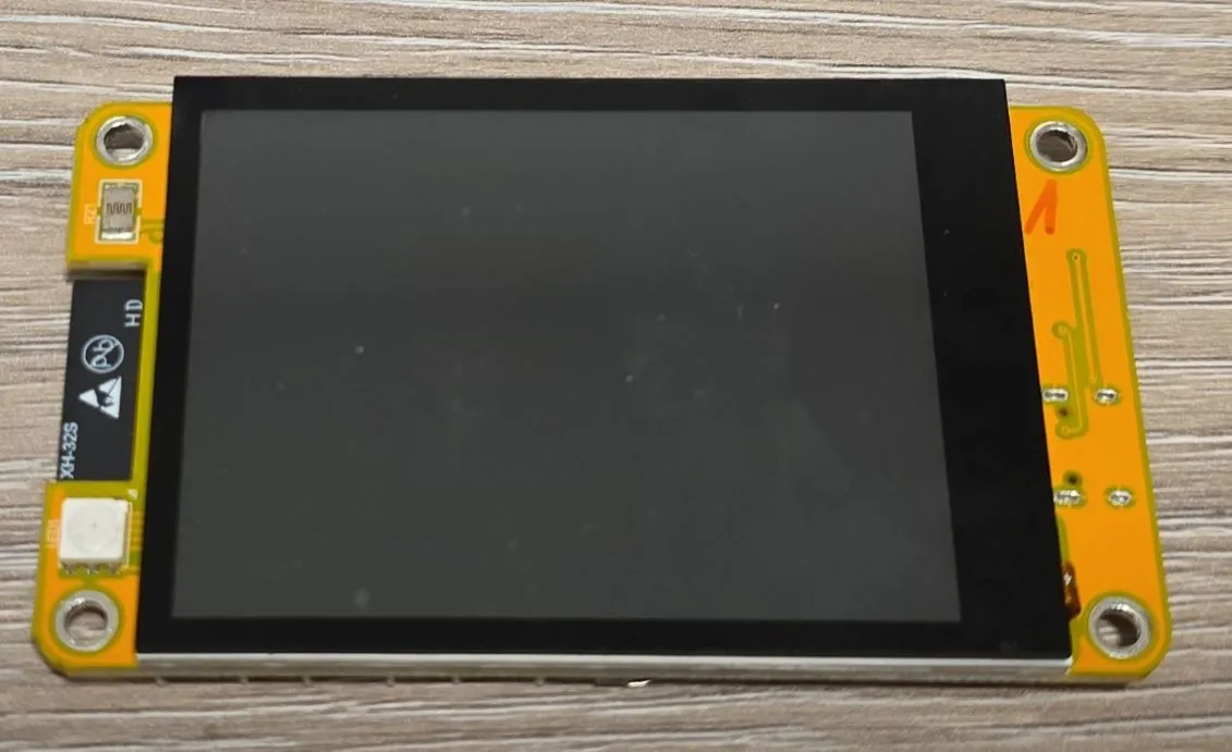
ESP32 development board with 2.8-inch 240x320 LCD, capacitive touchscreen, WiFi and Bluetooth
🚀 Used in Projects (1)
📐 See This Display in Action
This display is featured in our interactive size comparison.
🔲 See This Board in Action
This board is featured in our interactive size comparison.
Overview
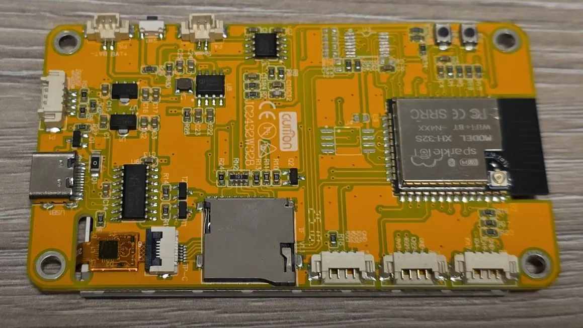
The Guition ESP32 JC2432W328C is a feature-rich development board combining an ESP32 module with a 2.8-inch 240x320 color LCD display and capacitive touchscreen. It includes WiFi, Bluetooth, RGB LED, speaker connector, SD card slot, photoresistor, and battery support, making it ideal for IoT projects requiring a user interface.
NOTE: This is covering only capacitive touch screen version, I haven’t tried resistive one. There is a different controller chip for resistive touch and wiring is slightly different I think. The calibration is slightly simpler with capacitive touch too.
The board uses the Sparkle IOT XH-32S module, which is based on the ESP-WROOM-32 with a dual-core Tensilica LX6 MCU running at 240MHz with 4MB Flash memory.
Test Status
Complete Example Configuration covers:
- ✅ Basic Config
- ✅ GPIO
- ✅ SPI (not exposed externally)
- ✅ I2C
- ✅ (LED) PWM (RGB LED & Backlight)
- ✅ ADC (Light Sensor)
- ✅ Display
- ✅ Touchscreen
The rest:
- SD-Card
- Speaker
- External Connectors
Hardware Features
- Display: 2.8” TFT LCD 240x320 (ST7789V controller)
- Touchscreen: Capacitive touch (CST816 controller)
- Connectivity: WiFi 802.11 b/g/n HT40, Bluetooth/BLE 4.2
- Storage: TF/Micro SD card slot
- Audio: Speaker connector (GPIO26)
- Sensors: Photoresistor (GPIO34)
- LED: RGB LED (GPIO4=Red, GPIO16=Green, GPIO17=Blue)
- Power: USB-C for programming and power, battery interface with switch, 4P 1.25 power supply base
- Buttons: Boot, Reset, Battery switch
- Backlight Control: GPIO27 (PWM controllable)
- USB: CH340C for USB-to-UART
Module Specifications
- Module: Sparkle IOT XH-32S (similar to ESP32-WROOM-32)
- CPU: Dual-core Xtensa 32-bit LX6, up to 240MHz
- RAM: 520KB SRAM
- Flash: 4MB
- WiFi: 802.11 b/g/n HT40
- Bluetooth: v4.2 BR/EDR and BLE
- Operating Voltage: 3.3V
- Input Voltage: 5V (USB-C or external)
Pinout and I/O Connectors
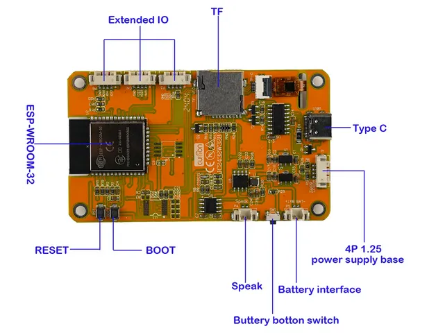
Switches and Buttons
- Reset (RST): resets the board
- Boot (BOOT): if low on startup, puts the board to programming mode. Not necessary to be used for programming, online ESPHome Web uses USB connection to put it into programming mode. The button can be used after startup as a normal button
- Battery Button Switch: Don’t press it if you are not using battery or you’ll reboot your device. My original enclosure was a bit tight and was pressing it slightly. Took me a while to figure out why is device not working
Extended I/O Connectors
Three 4-pin connectors provide access to additional GPIOs, from left to right looking at the back of the board (connectors are not named on the board but pin names are shown):
- CON1: GND, IO16, IO4, IO17 (RGB LED connections)
- CON2: GND, IO22, IO21, VCC (I2C interface)
- CON3: GND, IO32, IO22, IO21 (I2C + Touch I2C)
Pin Distribution
NOTE: Pins are marked as IOxx on the board, they correspond to GPIOs with the same number on the ESP32 chip. While you can define any pin in your configuration, not all are actually available and exposed on the board or have a function that could be useful.
| Pin | Function | Connected To | Notes |
|---|---|---|---|
| IO0 | BOOT | Boot button | |
| IO1 | U0TXD | Serial TX | |
| IO2 | GPIO | TFT_RS | Display DC pin |
| IO3 | U0RXD | Serial RX | |
| IO4 | GPIO | LED1_2 | RGB LED - Red (CON1) |
| IO5 | VSPI CS0 | TF_CS | SD Card CS |
| IO6 | SCK | Flash | Don’t use |
| IO7 | SDO | Flash | Don’t use |
| IO8 | SDI | Flash | Don’t use |
| IO9 | SHD/SD2 | Flash | Don’t use |
| IO10 | SWP/SD3 | Flash | Don’t use |
| IO11 | CSC/CMD | Flash | Don’t use |
| IO12 | HSPI MISO | TFT_SDO | Display SPI MISO |
| IO13 | HSPI MOSI | TFT_SDI | Display SPI MOSI |
| IO14 | HSPI CLK | TFT_SCK | Display SPI CLK |
| IO15 | HSPI CS0 | TFT_CS | Display SPI CS |
| IO16 | U2TXD | LED1_3 | RGB LED - Green (CON1) |
| IO17 | U2RXD | LED1_1 | RGB LED - Blue (CON1) |
| IO18 | VSPI CLK | TF_CLK | SD Card CLK |
| IO19 | VSPI MISO | TF_SDO | SD Card MISO |
| IO21 | I2C SDA | I2C Bus | CON2 & CON3 |
| IO22 | I2C SCL | I2C Bus | CON2 & CON3 |
| IO23 | VSPI MOSI | TF_SDI | SD Card MOSI |
| IO25 | GPIO | CTP_RST | Touch Reset |
| IO26 | GPIO | SPK | Speaker |
| IO27 | GPIO | BL_CTRL | Display Backlight PWM |
| IO32 | GPIO | CTP_SCL | Touch I2C SCL (CON3) |
| IO33 | GPIO | CTP_SDA | Touch I2C SDA |
| IO34 | INPUT ONLY | Photoresistor | Analog input |
| IO35 | INPUT ONLY | - | Not Exposed |
| IO36 | INPUT ONLY | - | Not Exposed |
| IO39 | INPUT ONLY | - | Not Exposed |
ESPHome Configuration
Complete Example Configuration
This is a complete example with all the hardware features configured:
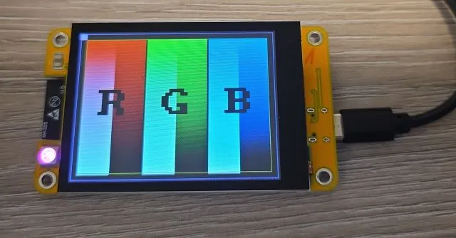
- RGB Screen is showing test card - check that R has red, G has green and B has blue background
- Touch Screen - see logs for coordinates of the touch, but easy visualisation - touch is turning backlight (and screen) on and off. If it toggles the screen, it’s working
- Backlight
- RGB light - all 3 colors set so you get some kind of pink. Comment out or change color percentages if you want a different color. Every 5 seconds brightness is changing just to show that controls are working
esphome:
  name: guition-display

esp32:
  board: esp32dev
  framework:
    type: esp-idf

logger:

interval:
  - interval: 5s
    then:
      # making sure that RGB light is wired up
      - light.turn_on: internal_rgb
      - light.control:
          id: internal_rgb
          brightness: !lambda |-
            static int num_executions = 0;
            num_executions = (num_executions % 4) + 1;
            //go from 10%-100%
            return num_executions * 0.25;
          red: 100%
          green: 25%
          blue: 75%

# Sensor for onboard photoresistor
# Check out log to see the read-outs
sensor:
  - platform: adc
    pin: GPIO34
    name: "Ambient Light"
    id: board_ldr
    update_interval: 60s
    attenuation: auto

# PWM outputs for RGB LED and backlight
output:
  - platform: ledc
    pin: GPIO04
    id: rgb_led_red
    inverted: true
  - platform: ledc
    pin: GPIO16
    id: rgb_led_green
    inverted: true
  - platform: ledc
    pin: GPIO17
    id: rgb_led_blue
    inverted: true
  - platform: ledc
    pin: GPIO27
    id: backlight_pwm

# RGB LED and backlight control
light:
  - platform: monochromatic
    output: backlight_pwm
    name: "Display Backlight"
    id: backlight
    restore_mode: ALWAYS_ON
  - platform: rgb
    id: internal_rgb
    name: "RGB LED"
    red: rgb_led_red
    green: rgb_led_green
    blue: rgb_led_blue
    restore_mode: ALWAYS_OFF

# Boot button
binary_sensor:
  - platform: gpio
    pin:
      number: GPIO00
      inverted: true
    name: "Boot Button"
    id: boot_btn

# SPI buses - separate for display and SD card
spi:
  - id: spi_card
    clk_pin: GPIO18
    mosi_pin: GPIO23
    miso_pin: GPIO19
  - id: spi_display
    clk_pin: GPIO14
    mosi_pin: GPIO13
    miso_pin: GPIO12

# Display configuration
display:
  - platform: mipi_spi
    model: ST7789V
    id: my_display
    spi_id: spi_display
    cs_pin: GPIO15
    dc_pin: GPIO02
    data_rate: 40MHz
    rotation: 90
    # for LGVL:
    #auto_clear_enabled: false
    #update_interval: never
    # only for initial testing to make sure the board is working
    show_test_card: true
    # have a look at different displays how to draw on the screen
    #lambda: |-
    #  // Your drawing code here
    #  it.print(0, 0, id(font), "Hello World!");

# I2C bus for touchscreen
i2c:
  id: i2c_bus
  sda: GPIO33
  scl: GPIO32

# Capacitive touchscreen
touchscreen:
  - platform: cst816
    id: my_touchscreen
    #NOTE: do not setup interrupt pin otherwise weird behavior
    reset_pin: GPIO25
    transform:
      swap_xy: true
      mirror_y: true
      mirror_x: false
    on_touch:
      - lambda: |-
          ESP_LOGI("touch", "x=%d, y=%d", touch.x, touch.y);
      #also turn on/off the screen on touch (just a visual so we know touch screen is wired up correctly)
      - light.toggle: backlight

# Optional: Speaker output
#output:
#  - platform: ledc
#    pin: GPIO26
#    id: speaker_out
#
#rtttl:
#  output: speaker_out
SD Card Configuration
To use the SD card slot:
spi:
  - id: spi_card
    clk_pin: GPIO18
    mosi_pin: GPIO23
    miso_pin: GPIO19

# Note: SD card support in ESPHome may require additional configuration
# Refer to ESPHome documentation for SD card component usageNOTE: I haven’t tested SD Card yet.
Touchscreen Calibration
The touchscreen may require calibration. Use the following code to display raw touch coordinates:
touchscreen:
  - platform: cst816
    id: my_touchscreen
    reset_pin: GPIO25
    on_touch:
      - lambda: |-
          ESP_LOGI("calibration", "x=%d, y=%d, x_raw=%d, y_raw=%d",
              touch.x, touch.y, touch.x_raw, touch.y_raw);
Adjust the transform parameters based on the output:
swap_xy: Swap X and Y coordinatesmirror_x: Mirror horizontallymirror_y: Mirror vertically
Important Notes
⚠️ SPI Buses: The board uses two separate SPI buses - one for the display (HSPI) and one for the SD card (VSPI). They are wired differently and not available for external devices.
⚠️ Flash Pins: GPIO6-11 are connected to the flash memory. Do not use these pins.
⚠️ Input-Only Pins: GPIO34-39 can only be used as inputs and don’t have internal pull-up/pull-down resistors. They are not exposed on the board anyway.
⚠️ RGB LED: The RGB LED pins are inverted (active low).
⚠️ Touch Reset: GPIO25 is used for touchscreen reset. Must be configured in the touchscreen component. Do not configure interrupt pin in the touchscreen component.
Using with LVGL
⚠️ Display Updates: For using with LVGL, set update_interval: never and auto_clear_enabled: false
in the display config.
This board works great with LVGL (Light and Versatile Graphics Library). To wake the display on touch:
touchscreen:
  - platform: cst816
    id: my_touchscreen
    reset_pin: GPIO25
    transform:
      swap_xy: true
      mirror_y: true
    on_release:
      - if:
          condition: lvgl.is_paused
          then:
            - logger.log: "LVGL resuming"
            - lvgl.resume:
            - lvgl.widget.redraw:
            - light.turn_on: backlight
Troubleshooting
Display not working:
- Check backlight is enabled (GPIO27)
- Verify SPI pins are correct (HSPI bus)
- Try lower data_rate (start with 10MHz, then increase)
Touch not responding:
- Verify I2C pins (GPIO32=SCL, GPIO33=SDA)
- Check touchscreen reset pin (GPIO25) is configured
- Do not configure interrupt pin
- Run I2C scan to confirm CST816 is detected
Board won’t flash:
- Hold the BOOT button while connecting USB
- Try a different USB cable (must support data)
- Ensure USB drivers are installed
- It uses CH340C - I noticed only one serial port showing up even when multiple boards connected, disconnect other boards
Random resets:
- Check power supply (needs stable 5V, 500mA+)
- If using battery, ensure it’s charged
- Disable WiFi temporarily to test if power-related
Other Images