Adafruit MiniPiTFT 1.3"
240x240 TFT Color display with ST7789 driver and 2 buttons
Connection Types
📐 See This Display in Action
This display is featured in our interactive size comparison.
Overview
The Adafruit MiniPiTFT is a 1.3” (diagonal) TFT display with 240x240 pixel resolution, featuring the ST7789 display driver and two tactile buttons. Originally designed for Raspberry Pi, it works with ESP32 and other microcontrollers.
The module features:
- 1.3” square TFT display (240x240 pixels)
- ST7789 display driver
- 4-wire SPI interface
- Full color display (RGB 18-bit, 262K colors)
- 2x tactile buttons (on model #4393)
- Bright backlight
Testing Status
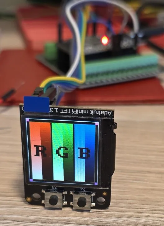
- ✅ Basic Config - Wiring up & Test Card in Color
- ✅ Backlight
- ✅ Buttons
- ✅ Simple Graphics and Text
- ✅ Multipage Icons and Text 🌈🦾
Configuration Notes
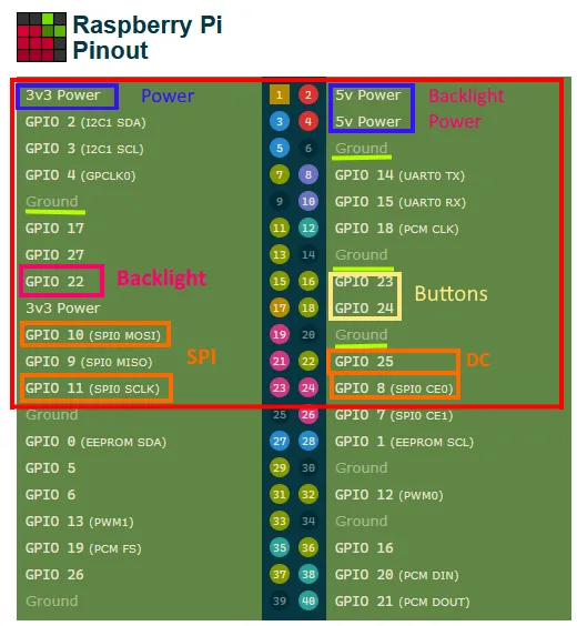
The mini PiTFT connects to the ‘top’ 2x12 headers on the Pi’s 2x20 header connection. It uses the following pins:
- 5.0V - Connected to the display backlight - NOTE ⚠️: this is incorrectly stated at the pinout page. the schematic shows that the backlight is connected to 3.3V
- 3.3V - Connected to the display power and also the STEMMA QT / Qwiic connector
- GND - Ground for everything
- SDA & SCL - I2C data for the STEMMA QT / Qwiic connector. Not used by buttons or display - we won’t use it since this is only relevant for Raspberry Pi connection. We could connect I2C to these pins and expose I2C through that STEMMA QT / Qwiic connector if needed
- GPIO22 (BL) - Used to turn the backlight on and off. If you never want to turn the backlight off, cut the small jumper on the bottom of the PiTFT to free up GPIO22. This advice is if you’re using Raspberry Pi
- GPIO23 & GPIO24 - Connected to the two front buttons. These pins have 10K pullups to 3.3V so when the button is pressed, you will read a LOW voltage on these pins. So they need to be configured as inverted
- SCK, MOSI, CE0 & GPIO25 (DC) - These are the display control pins. Note that MISO is not connected even though it is a SPI pin because you cannot read back from the display.
ST7789 display driver supported through MIPI SPI. ST7789V component is still available but will be removed in future.
NOTE: On the panel’s datasheet it actually says ST7789V.
Wiring
Example here is for esp32-devkit-v1 Adjust substitutions based on your board. For the examples below I used the following wiring:
| 1.3” LCD | esp32-devkit-v1 | Notes |
|---|---|---|
| GPIO 22 | GPIO25 | BLK |
| GPIO 8 (SPI0 CE0) | GPIO05 | CS |
| GPIO 25 | GPIO04 | DC |
| GPIO 10 (SPI0 MOSI) | GPIO23 | MOSI |
| GPIO 11 (SPI0 SCLK) | GPIO18 | SCK |
| GPIO 23 | GPIO26 | Button 1 |
| GPIO 24 | GPIO27 | Button 2 |
| VCC | 3V3 | |
| GND | GND |
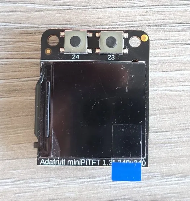
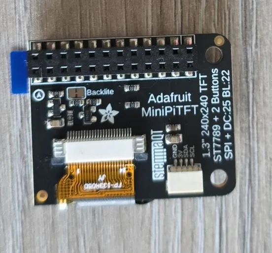
WARNING 🤦♂️: I spent a good bit of time figuring out why the display did not work. The diagram above is the top view (looking from above). And, there’s a marking on the back of the display that I took to be pin number 1 - that’s incorrect. I marked here which is the pin number 1:

Basic Configuration
Show test card - ensures everything is correctly configured and wired up. Note that the display is square so rotation is not really necessary. I just wanted buttons to be under the display, so had to rotate it 90 degrees.
Also note that ST7735V supports 320x240 resolution, width and height have to specified. Offsets are not needed since they are 0 (great job 👍) but I thought to include them for completeness. Some other displays do need it like the small RGB LCDE from Pimoroni.
esphome:
  name: my-display-test

esp32:
  variant: esp32
  framework:
    type: esp-idf
    advanced:
      minimum_chip_revision: "3.1"

logger:

substitutions:
  clk_pin: GPIO18
  mosi_pin: GPIO23
  disp_cs_pin: GPIO05
  disp_dc_pin: GPIO04
  backlight_pin: GPIO25
  btn_1_pin: GPIO26
  btn_2_pin: GPIO27

spi:
  clk_pin: ${clk_pin}
  mosi_pin: ${mosi_pin}

display:
  - platform: mipi_spi
    id: my_display
    model: ST7789V
    cs_pin: ${disp_cs_pin}
    dc_pin: ${disp_dc_pin}
    show_test_card: true
    data_rate: 40MHz
    rotation: 90
    invert_colors: true
    dimensions:
      width: 240
      height: 240
      offset_height: 0
      offset_width: 0
Adding Backlight Support & Buttons
The following code wires up backlight and uses two buttons to increase and decrease brightness by 25%.
globals:
  - id: backlight_level
    type: int
    restore_value: no
    initial_value: '5'

binary_sensor:
  - platform: gpio
    id: button1
    pin:
      number: ${btn_1_pin}
      inverted: true
    on_click:
      then:
        - if:
            condition:
              - lambda: return id(backlight_level) > 1;
            then:
              - globals.set:
                  id: backlight_level
                  value: !lambda return id(backlight_level) - 1;
              - light.turn_on: backlight
              - light.control:
                  id: backlight
                  brightness: !lambda return id(backlight_level) * 0.2;
            else:
              - globals.set:
                  id: backlight_level
                  value: '0'
              - light.turn_off: backlight
  - platform: gpio
    id: button2
    pin:
      number: ${btn_2_pin}
      inverted: true
    on_click:
      then:
        - if:
            condition:
              - lambda: return id(backlight_level) < 4;
            then:
              - globals.set:
                  id: backlight_level
                  value: !lambda return id(backlight_level) + 1;
            else:
              - globals.set:
                  id: backlight_level
                  value: '5'
        - light.turn_on: backlight
        - light.control:
            id: backlight
            brightness: !lambda return id(backlight_level) * 0.2;

output:
  - platform: ledc
    pin: ${backlight_pin}
    id: backlight_pwm

light:
  - platform: monochromatic
    output: backlight_pwm
    name: "Display Backlight"
    id: backlight

display:
  - platform: mipi_spi
    id: my_display
    model: ST7789V
    cs_pin: ${disp_cs_pin}
    dc_pin: ${disp_dc_pin}
    show_test_card: true
    data_rate: 40MHz
    rotation: 90
    invert_colors: true
    dimensions:
      width: 240
      height: 240
      offset_height: 0
      offset_width: 0
Simple Graphics and Text Example
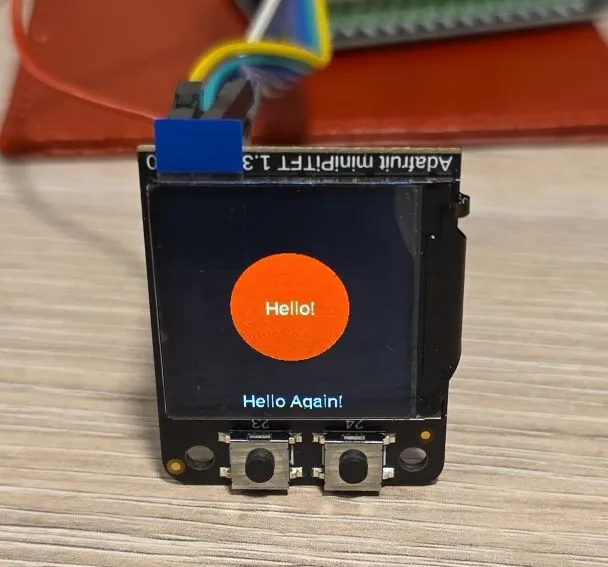
To add text and graphics, add the lambda section and define fonts to the basic config:
In the real life, the circle is full red, camera doesn’t do it justice
font:
  - file: "gfonts://Roboto"
    id: roboto
    size: 20

display:
  - platform: mipi_spi
    id: my_display
    model: ST7789V
    cs_pin: ${disp_cs_pin}
    dc_pin: ${disp_dc_pin}
    data_rate: 40MHz
    rotation: 90
    invert_colors: true
    dimensions:
      width: 240
      height: 240
      offset_height: 0
      offset_width: 0
    lambda: |-
      it.filled_circle(it.get_width()/2, it.get_height()/2, 60, Color(0xFF0000));
      it.print(it.get_width()/2, it.get_height()/2, id(roboto), Color(0x00FF78), TextAlign::CENTER, "Hello!");
      it.print(it.get_width()/2, it.get_height()-10, id(roboto), Color(0xFFFFFF), TextAlign::CENTER, "Hello Again!");
Icons, Text, Pretty
This example has 4 different pages and changes them on button click. The display is set not to update itself
because updates are only done on button click. You might want to change update_interval: never to some
other value (default is 1s = 1 second) unless you’re using LVGL which handles display itself.
Both buttons, backlight and display are configured.
WARNING ⚠️: Set restore_mode: ALWAYS_ON for backlight otherwise you won’t see anything on the screen unless
you connect it to Home Assistant and can turn it on from there.
binary_sensor:
- platform: gpio
id: button1
pin:
number: ${btn_1_pin}
inverted: true
on_click:
then:
- display.page.show_previous: my_display
- component.update: my_display
- platform: gpio
id: button2
pin:
number: ${btn_2_pin}
inverted: true
on_click:
then:
- display.page.show_next: my_display
- component.update: my_display
output:
- platform: ledc
pin: ${backlight_pin}
id: backlight_pwm
light:
- platform: monochromatic
output: backlight_pwm
name: "Display Backlight"
id: backlight
restore_mode: ALWAYS_ON
font:
#color screen, so good for anti-aliasing
- id: value_med
file:
type: gfonts
family: Montserrat
size: 14
bpp: 4
- id: value_small
file:
type: gfonts
family: Montserrat
size: 10
bpp: 2
- id: value_large
file:
type: gfonts
family: Montserrat
weight: bold
size: 20
bpp: 4
- id: mdi_small
file: assets/materialdesignicons-webfont.ttf
size: 24
bpp: 4
glyphs: [
"\U000F1A71", # snowflake-thermometer
"\U000F032A", # leaf
"\U000F04B9", # sofa
"\U000F14DE", # rocket-launch
"\U000F0C52", # checkbox-outline
"\U000F0158", # close-box-outline
"\U000F0704", # plus-box-outline
"\U000F06F2", # minus-box-outline
]
- id: mdi_med
file: assets/materialdesignicons-webfont.ttf
size: 64
bpp: 4
glyphs: [
"\U000F1807", # mdi-fire-circle
"\U000F0E1B", # mdi-car-back
]
- id: mdi_large
file: assets/materialdesignicons-webfont.ttf
size: 96
bpp: 4
glyphs: [
"\U000F0593", # lightning
"\U000F1A71", # snowflake-thermometer
"\U000F032A", # leaf
"\U000F04B9", # sofa
"\U000F14DE", # rocket-launch
]
display:
- platform: mipi_spi
id: my_display
model: ST7789V
cs_pin: ${disp_cs_pin}
dc_pin: ${disp_dc_pin}
show_test_card: true
data_rate: 40MHz
rotation: 90
invert_colors: true
dimensions:
width: 240
height: 240
offset_height: 0
offset_width: 0
# only update on button click for this demo
update_interval: never
pages:
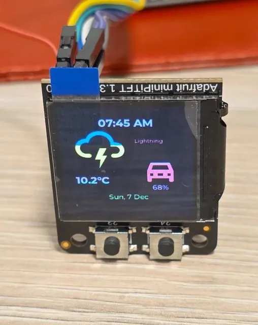
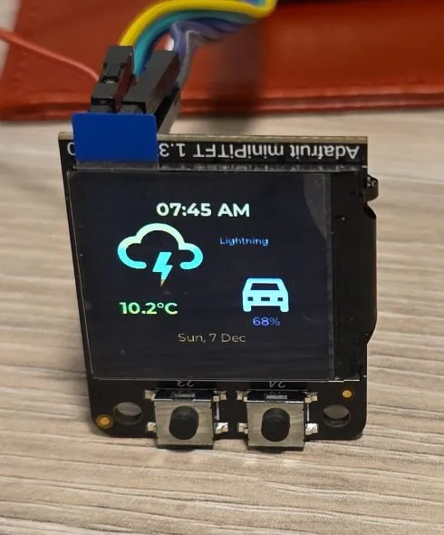
- id: page_info
lambda: |-
//print time and date
it.print(it.get_width()/2, 32, id(value_large), Color::random_color(), TextAlign::CENTER, "07:45 AM");
it.print(it.get_width()/2, 194, id(value_med), Color::random_color(), TextAlign::CENTER, "Sun, 7 Dec");
it.print(24, 42, id(mdi_large), Color::random_color(), "\U000F0593");
it.print(160, 64, id(value_small), Color::random_color(), TextAlign::TOP_CENTER, "Lightning");
it.print(24, 144, id(value_large), Color::random_color(), "10.2°C");
it.print(180, 104, id(mdi_med), Color::random_color(), TextAlign::TOP_CENTER, "\U000F0E1B");
it.print(180, 164, id(value_med), Color::random_color(), TextAlign::TOP_CENTER, "68%");
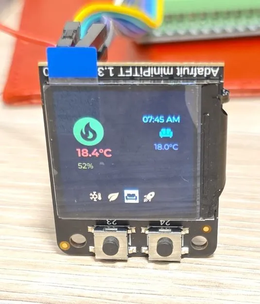
- id: page_heating
lambda: |-
const std::string presets[] = {
"frost", "eco", "comfort", "boost"
};
const std::string icons[] = {
"\U000F1A71", "\U000F032A", "\U000F04B9", "\U000F14DE"
};
it.print(it.get_width() - 24, 42, id(value_med), Color(0x87CEEB), TextAlign::TOP_RIGHT, "07:45 AM");
it.print(24, 42, id(mdi_med), Color(0x228B22), "\U000F1807");
it.print(32, 102, id(value_large), Color(0xDC143C), "18.4°C");
it.print(32, 132, id(value_med), Color(0xDAA520), "52%");
it.print(it.get_width() - 48, 102, id(value_med), Color(0xBA55D3), TextAlign::CENTER, "18.0°C");
it.print(it.get_width() - 48, 76, id(mdi_small), Color(0x008080), TextAlign::CENTER, "\U000F04B9");
//show icons
const int icon_size = 24;
auto y = it.get_height() - 2*icon_size;
for(auto i = 0; i<4; i++){
auto is_selected = "comfort" == presets[i];
auto x = 48 + icon_size*i + 9*i; auto invert_icon = false;
if(is_selected){
invert_icon = true;
it.filled_rectangle(x, y-1, icon_size+1, icon_size+1);
}
it.print(x, y, id(mdi_small), invert_icon ? COLOR_OFF : Color(0xF4A460), icons[i].c_str());
}
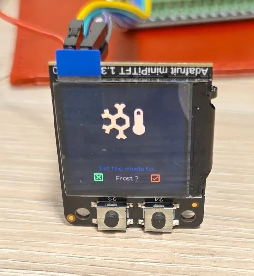
- id: page_change_preset
lambda: |-
it.print(it.get_width()/2, it.get_height()/2, id(mdi_large), Color(0xF4A460), TextAlign::BOTTOM_CENTER, "\U000F1A71");
it.print(it.get_width()/2, it.get_height()-68, id(value_med), Color(0x000080),
TextAlign::TOP_CENTER, "Set the mode to:");
it.print(it.get_width()/2, it.get_height()-44, id(value_med), Color(0xF08080),
TextAlign::TOP_CENTER, "Frost ?");
//apply
it.print(48, it.get_height() - 48, id(mdi_small), Color(0x00FF00), TextAlign::TOP_LEFT, "\U000F0158");
//cancel
it.print(it.get_width()-48, it.get_height() - 48, id(mdi_small), Color(0xFF0000), TextAlign::TOP_RIGHT, "\U000F0C52");
- id: page_change_temp
lambda: |-
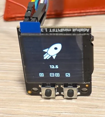
it.print(it.get_width()/2, it.get_height()/2, id(mdi_large), COLOR_ON, TextAlign::BOTTOM_CENTER, "\U000F14DE");
it.print(it.get_width()/2, it.get_height()-96, id(value_large), COLOR_ON, TextAlign::TOP_CENTER, "12.5");
//apply
it.print(48, it.get_height() - 48, id(mdi_small), COLOR_ON, TextAlign::TOP_LEFT, "\U000F0158");
//cancel
it.print(it.get_width()-48, it.get_height() - 48, id(mdi_small), COLOR_ON, TextAlign::TOP_RIGHT, "\U000F0C52");
//minus
it.print(96, it.get_height() - 48, id(mdi_small), COLOR_ON, TextAlign::TOP_LEFT, "\U000F06F2");
//plus
it.print(it.get_width() - 96, it.get_height() - 48, id(mdi_small), COLOR_ON, TextAlign::TOP_RIGHT, "\U000F0704");Other Images
Back of the LCD Display:
- Page 1 - Info Screen (configured for random colors so another shot)
- Page 2 - Heating Screen
- Page 3 - Set Heating Preset
- Page 4 - Set Boost Temperature